Use of Automatic Vehicle Monitoring, Vehicle Health Monitoring, and Diagnostic Systems by Transit Agencies (2025)
Chapter: 1 Introduction

CHAPTER 1
Introduction
Background
Automatic Vehicle Monitoring (AVM) began its venture into the transit world in 1994—30 years before the onset of this study. Specialists wanted to gain a better understanding of the technologyʼs present and future capabilities, which led to a variety of studies around the world. The early studies proved that the technology should be explored and advanced further. The studies also indicated that the technology should be more accessible and affordable for use by transit agencies.
In 2010, TCRP published a synthesis that organized and consolidated available information that was fragmented across many studies (Schiavone 2010). In the last few years, AVM, VHM, and PMT have become increasingly integrated in many transit agencies across the United States and the world.
This TCRP synthesis study was initiated to learn from individual agencies that utilize this technology in areas such as how they deployed it into their agency, what training was required to carry it out, how the integration process took place, what benefits have been seen, and what lessons were learned from the process. TCRPʼs goal is for this study to encourage more agencies to use this technology in a way that fits their unique needs.
Key Terminology
The following definitions are provided for key terms used throughout this synthesis:
- Artificial intelligence (AI): An evolving and important tool that enables technology to augment human tasks and perform tasks humans cannot or will not do (Ray 2023). Note: The definition of AI varies among its users and industries. The description offered here is viewed as a traditional and unbiased definition of the term.
- Automatic vehicle location (AVL): An electronic system that provides the real-time location of a vehicle using Global Positioning System (GPS) technology.
- Automatic vehicle monitoring (AVM): An electronic system that provides real-time information about a vehicle—including its location, speed, and other vital statistics.
- Computer-aided dispatch (CAD): A software application that allows users to perform dispatching operations from a computer.
- Controller area network (CAN): A vehicle standard that allows for communication between microcontrollers and devices.
- Original equipment manufacturer (OEM): A company whose goods are used (and can be marketed) as components in the products of another company.
- Predictive maintenance technology (PMT): Vehicle monitoring technology that optimizes the performance and lifespan of equipment by continually assessing its health in real time.
- Telematics: An interdisciplinary field encompassing telecommunications; vehicular technologies (e.g., road transport, road safety); electrical engineering (e.g., sensors, instruments, wireless communications); and computer science.
- Vehicle health monitoring (VHM): Vehicle technology designed to track, monitor, and manage individual vehicles or entire fleets with the objective of enhancing safety, improving operational efficiency, optimizing routes, managing vehicle maintenance, and providing insights into driver behavior.
Purpose
The purpose of this study is to explore how AVM, VHM, diagnostic systems, and PMT are utilized to monitor an array of onboard vehicle components in order to assist in the early identification of potential mechanical issues, thus supporting effective maintenance practices. Sensors monitor the performance of various engine and vehicle components and systems. This functionality takes on different forms and levels of sophistication or integration. These variations include the following:
- An integrated comprehensive vehicle monitoring, diagnostic, and reporting system that is built into the maintenance system. The system may be fully integrated with the onboard CAD/AVL system, or it may be a stand-alone telematics system.
- Vehicle engine and component suppliers that provide their own independent diagnostic systems to be used by maintenance departments.
- A limited number of engine sensors integrated into the AVL system that solely provide real-time alarms for faults or critical failures (e.g., temperature, pressure).
Comprehensive vehicle monitoring and health diagnostic systems can be used to predict and identify potential mechanical failures and promote accuracy and efficiency within a transit agencyʼs maintenance department. Monitoring systems have the ability to provide an itemized and prioritized report of vehicle faults, helping a maintenance department to determine which issues to work on first. The early identification of such faults through expanded onboard monitoring allows an agency to respond more quickly with its predictive maintenance action. This maintenance effort would typically not take place until the next scheduled preventive maintenance interval or after a sudden breakdown had occurred. The systems also allow for the direct assignment of personnel to required repair actions, eliminating major costs associated with the labor of diagnostic time. Specific components are identified as well, which decreases costs related to the purchased components of a misdiagnosed issue. The purpose of this study is to explore how agencies across the United States currently utilize AVM, VHM, diagnostic systems, and PMT as well as to provide an in-depth understanding of how these technologies can be used to benefit each individual transit agency.
Objectives
The main objective of this synthesis is to document the current use and benefits of using comprehensive vehicle monitoring and health diagnostic systems as part of enhanced and data-driven maintenance practice for heavy-duty buses. Subsequent objectives include studying, analyzing, and identifying the following:
- The types of data used for maintenance practices
- The extent of the use of AI and comprehensive vehicle monitoring systems in the transit industry
- Whether the systems are integrated into the CAD/AVL platform or are stand-alone telematics systems
- The ways in which comprehensive vehicle monitoring systems have changed maintenance procedures in areas where they have been deployed
- The challenges to integration and deployment of the technology
Description of Technologies
This section discusses the evolution of diagnostic technology and of standards for vehicles. Engine and bus diagnostic technology has evolved exponentially over the past few decades. The journey started with mechanical engines and controls, which have transitioned from CAN wiring to fully electronic communication and controls. These are compliant with successive SAE International (SAE was formerly known as the Society of Automotive Engineers) standards. These electronic networks alert the driver or maintenance team (and later inform the technician) of any abnormality in operations. The sensor data are now often coupled with operational (bus, route, and block) and location data and are transmitted to the base either through AVM or telematics. These systems gather a plethora of data points (referred to as “big data”) that can be processed and analyzed to anticipate component failure, warn maintenance departments of failure probability, and provide repair plans. Finally, the big data from AVM can now be processed in Artificial Intelligence Predictive Maintenance systems, applying machine learning to anticipate component failure.
Telematics, AVM, and Predictive Maintenance
Individual systems have a complicated legacy of custom ordering their transit vehicles. As a result, depending on its duty cycle, a transit bus is often distinct to a particular agency. There was a shift in the past few years from standardized buses from companies that have traditionally produced them to buses manufactured by newer companies. There exist far fewer OEMs for buses at the time of this publication than there were two or three years ago.
Currently, transit buses comprise many parts that are produced by several different companies and assembled by an OEM. The primary subsystems of a bus are provided by component manufacturers, which develop useful products that fit together to make a transit bus. Over the past 20 years, there were several technological trends powering the economy—semiconductors, wireless technology, cloud computing, and AI—all of which have been pertinent to transit buses. In the next 10 years, many innovations specific to vehicles are anticipated. These include battery electric propulsion, hydrogen-powered propulsion, and autonomous technologies.
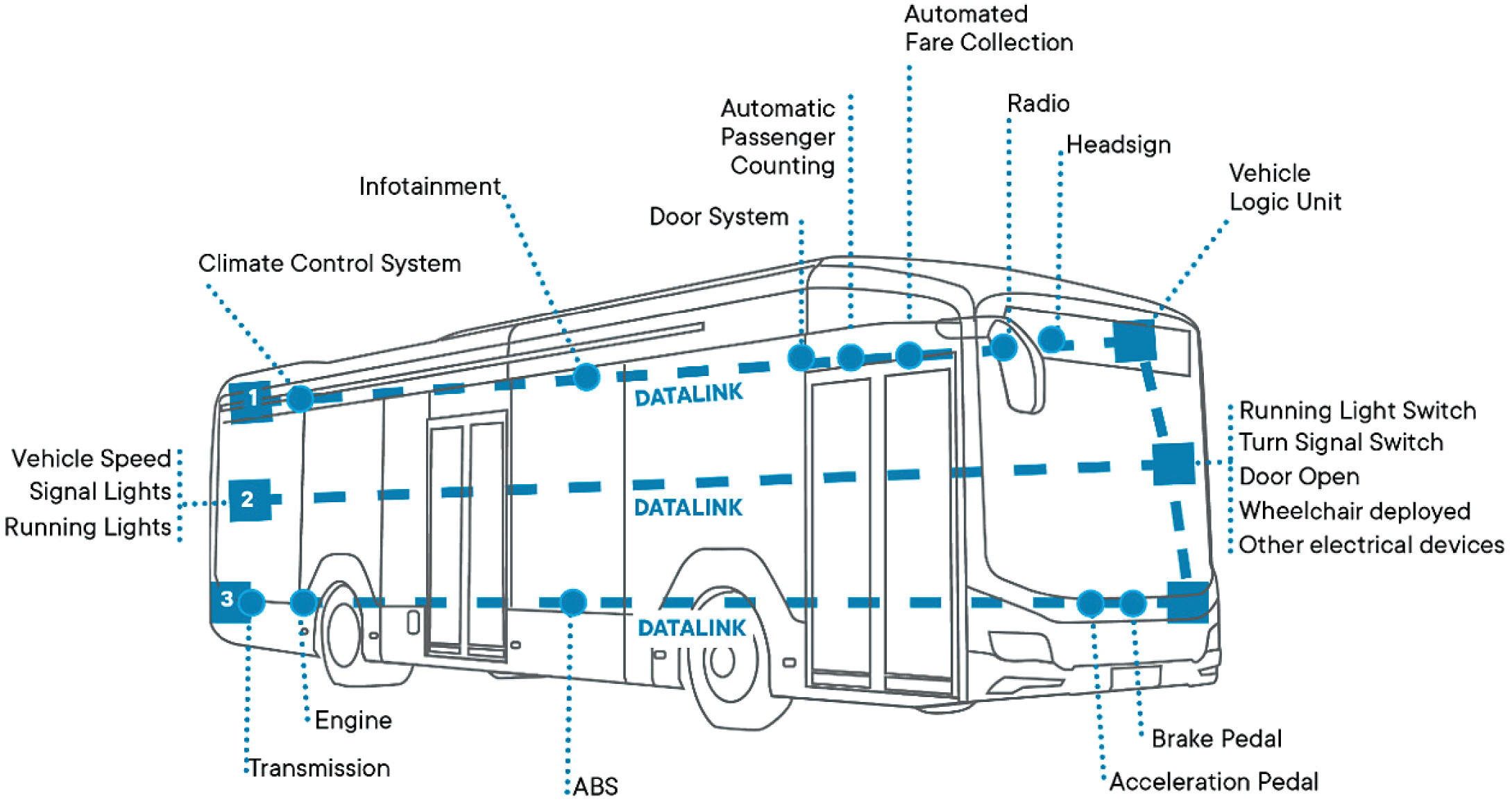
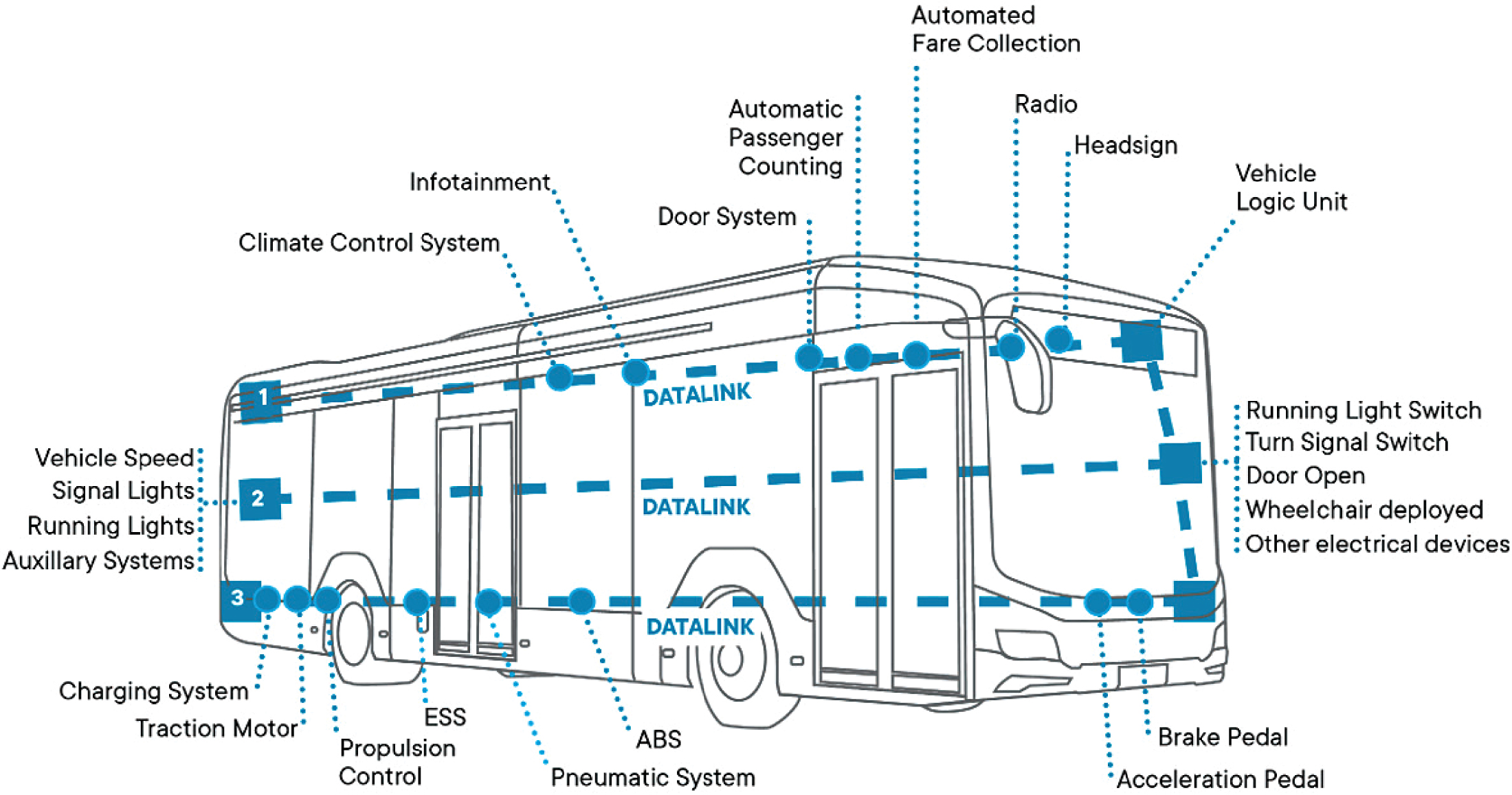
Figures 1 and 2 show a diesel bus and a battery electric bus (BEB), respectively, with labels included to provide a better understanding of each component and its purpose. Please note that ABS stands for antilock braking system and ESS stands for energy storage system. The latter is for BEBs only.
For more information on bus components and systems, including their specific purposes, see the tables in Appendix A. These tables provide additional information on vehicle signals, engine, transmission, multiplex system broadcast via J1939 CAN Network, brake system (ABS), door systems, climate control systems, arctic joint system, electric vehicle data elements, vehicle logic unit, powertrain system, charging system, electric vehicle pneumatic system, electric vehicle heating, ventilation, and air conditioning (HVAC) system, and electric vehicle auxiliary systems.
Wireless technologies allow for the transport of data outside the transit bus. The niche that is significant here is the Internet of Things (IoT). IoT allows semiconductors to transmit data from the transit bus affordably and in unimaginable quantities. IoT also allows for the development of applications like CAD/AVL, Wi-Fi connectivity, and PMT. Cloud computing allows for the storage of large quantities of data at low cost and for computation using each of the data points. Cloud computing enables the creation of a “digital twin.” A digital twin is a virtual model of an intended or real-world physical product, system, or process (known as the “physical twin”). The digital twin serves as the physical twinʼs digital counterpart and can be used for purposes such as simulation,
Long Description.
The illustration shows an outline of a bus. The bus shows three horizontal dotted lines numbered 1, 2, and 3. The first line at the top of the bus indicates the following, marked from the back to the front with dots. They are as follows: Climate control system, Infotainment, Door system, Automatic passenger counting, Automated fare collection, Radio, Headsign, and Vehicle logic unit. The second line (in the middle) is as follows: Vehicle speed, Signal lights, and Running lights all in the back of the bus, and Running light switch, Turn signal switch, Door open, Wheelchair deployed, and Other electrical devices in the front of the bus. The third line (at the bottom) shows (back to front): Transmission, Engine, ABS, Acceleration pedal, and Brake pedal. All three lines are marked as Datalink.
Long Description.
The illustration shows an outline of a bus. The bus shows three horizontal dotted lines numbered 1, 2, and 3. The first line at the top of the bus indicates the following, marked from the back to the front with dots. They are as follows: Climate control system, Infotainment, Door system, Automatic passenger counting, Automated fare collection, Radio, Headsign, and Vehicle logic unit. The second line (in the middle) is as follows: Vehicle speed, Signal lights, Running lights, Auxiliary systems in the back of the bus, Running light switch, Turn signal switch, Door open, Wheelchair deployed, and Other electrical devices in the front of the bus. The third line (at the bottom) shows (back to front): Charging system, Traction motor, Propulsion control, ESS, Pneumatic system, ABS, Acceleration pedal, and Brake pedal. All three lines are marked as Datalink.
integration, testing, monitoring, and maintenance. AI leverages cloud storage to create unique and focused algorithms using data science and machine learning technologies. These algorithms can assist with developing early warning insights on the performance of parts of a transit bus.
The sensor data that each subsystem generates is combined and processed using AI technology. The data are based on standards established by SAE. SAE has created common standards (standards J1708 and J1939) for sensor data that can be retrieved so that maintenance insights can be gained. These sensors are assigned a Suspect Parameter Number and Parameter Group Number and provide indications of what is happening on various subsystems of a transit bus. Diagnostic fault codes are also created by transit bus systems to provide information to the driver and agency on potential safety- or emissions-related alerts.
CAD/AVL technologies are specific to the transit industry; they have led to significant innovation in tracking, managing, and scheduling buses. CAD/AVL systems can operate through a Wi-Fi router once a transit bus returns to its facility. In some instances, a wireless Subscriber Identity Module (SIM) can be used.
Telematics technologies are primarily used in trucking and passenger cars and have several applications, but they do not have all of the robust applications that CAD/AVL has for transit buses. Telematics hardware comes with a wireless SIM that allows for applications such as tracking and electronic logs. CAD/AVL and AVM systems have created large quantities of big data. These data require analysis by a vast and dedicated team, which is a big undertaking.
A PMT application can take gathered sensor data that are transmitted in CAD/AVL and AVM (an estimated one million sensor data points per day per transit bus) and run it through machine learning algorithms on the cloud. PMT has the capability to assist with early warnings on component failures or to predict road calls. This occurs from a combination of several algorithms and from learning not only from transit buses but also from heavy-duty trucks that operate in cities (e.g., garbage trucks).
Only since 2020 have cost and technology provided the environment needed to develop AI-driven PMT. By predicting and preventing breakdowns, safety and operations are improved, thus leading to a reduction in labor and maintenance costs. The precise scheduling of repairs can help reduce failures, and component usage can be trimmed. This technology enables technicians to repair a potential failure proactively and correctly the first time, with the help of accurate failure analysis by AI. The companies with AVM technologies in transit include, but are not limited to, Clever Devices (AVM); Conduent (OrbCAD); INIT (VHM); Preteckt; and Vontas (Trapeze Vehicle Intelligence).
These products come from companies that serve the transit industry, and most of them are integrated with CAD/AVL. Preteckt is a stand-alone AI company that can work with telematics or with CAD/AVL companies.
As transit agencies make the transition to zero emissions vehicles, PMT has the potential to save money by reducing battery- or fuel cell-related failures, help with range improvement, and avoid thermal events by remotely monitoring the batteriesʼ temperature levels. The storage of historical operational data in the cloud will be critical for insurance and warranty claims as this technology continues to evolve.
History of CAN Messaging
A CAN is a vehicle standard that allows for the communication of microcontrollers and devices. For each device, the data in a frame are transmitted in succession; if more than one device transmits data at the same time, the highest priority device is the one that continues.
Formerly, automobile manufacturers would connect various electronic devices in vehicles using several wires through point-to-point connections. This resulted in large collections of wire connections, which were complex and costly. Later, this complicated wiring system was replaced with the CAN, which is a dedicated wiring system intended to enhance communication speed between devices and provide a higher level of data integrity. This wiring system is often referred to as a “CAN bus.” The CAN was first developed by Bosch in 1985 for in-vehicle networking purposes. Todayʼs vehicles are mobile networks of sensors, controllers, and automation components that are linked on what is generally described as the vehicle “bus.” In the physical world, the bus is simply a pair of wires connecting all of a vehicleʼs electronic modules. In the world of electronic data, the bus carries various types of messages that are formatted to report status, issue commands, and request data. The moduleʼs interpretation of these data depends on established protocols; these can vary by vehicle depending on the vehicleʼs manufacturer, model, weight, and model year. CAN is a message-based protocol that is designed to provide reliable communication between multiple electronic control units (ECUs). It is a serial networking technology. Through CAN messaging, various microcontroller devices can have real-time communication without the need for a hosting computer. The protocol features unique identifiers that provide data about the urgency and significance of the transmitted message. This has the benefits of reducing vehicle wiring and of allowing for the addition or removal of further vehicle options. Troubleshooting a complex system is relatively straightforward once the technician has a basic understanding of the network and how data are transferred.
Development of SAE J1708 and SAE J1939 Standards
CAN messaging only provides a basis for communication (similar to that of a telephone); it does not provide a language for conversation. In the 1990s, SAE promoted SAE J1708 as a standard of serial communication for heavy-duty trucks and buses. This protocol is maintained by SAE. SAE J1708 is a set of standards that define how ECUs communicate through CAN messaging in heavy-duty vehicles. With respect to the Open System Interconnection model (OSI), SAE J1708 defines the physical layer (wiring), and SAE J1587 and SAE J1922 operate on top of J1708 as the message layer or data format. In the early 1990s, this was put into production vehicles as the standard. Beginning in 1995, it included a specific diagnostic connector intended for use on all heavy-duty vehicles. This connector, commonly referred to as the 6 Pin Deutsch connector, provided access to a vehicleʼs CAN messaging along with battery power and ground connections, with an option for a connection to proprietary networks available on the vehicle.
After the standardʼs release, it became evident that SAE J1708ʼs network speed of 9,600 bits per second limited the amount of data and sophistication that could be included in a heavy-duty vehicle. The members of SAE determined that a higher-speed network would be required and began to draft the standard that would become known as SAE J1939. Quickly evolving to adopt the CAN standards used by light-duty vehicle manufacturers in the 1980s, SAE J1939 customized the requirements for physical connections and data elements in order to meet the requirements of the heavy-duty vehicle environment. With SAE J1939, data rates were now up to 250 Kbits/s, and more control modules were supported in the network. By 2005, most heavy-duty truck and engine manufacturers had adopted at least a partial implementation of SAE J1939. SAE J1939 also has its own unique connector. Although it was still referred to as a Deutsch plug, this one was changed to nine pins. It continued to have power, ground, and SAE J1708 connections in addition to the new SAE J1939 wires. It also added the option for a second CAN connection for proprietary data networks.
Although market demand for vehicle electronics is driving innovation and complexity, networked vehicles originated from government requirements to control and regulate vehicle emissions and
reduce air pollution. Soon after these regulations were implemented, multiple studies showed that adding sophisticated features such as antilock brakes led to an increase in safety. Adding these regulations soon led to the addition of hardware and software as standard features on every vehicle.
SAE J1939 is important because it provides a common language across manufacturers. J1939 has continued to evolve, and it will soon be upgraded to a 500 Kbits/s network based on a new standard (SAE J1939-14).


