Evaluating Crashworthiness of Sign Supports and Breakaway Luminaire Poles: Appendices (2024)
Chapter: Appendix J: Summary for Test No. 23012
APPENDIX J
Summary for Test No. 23012
CRASH TEST EVALUATION OF A SMALL SIGN
SUPPORT SYSTEM –
SMALL CAR AT 100 KM/HR IMPACT
Authors:
Dhafer Marzougui, Christopher Story
Fadi Tahan, and Cing-Dao (Steve) Kan
Center for Collision Safety and Analysis
George Mason University
FOIL Test No. 23012
CCSA Report No. R-23012
Sponsored by:
Federal Highway Administration
U.S. Department of Transportation
and
National Cooperative Highway Research Program
Transportation Research Board
of The National Academies
July 2023
SUMMARY
This document reports the result of a crash test described below:
| Report Title | Crash Test Evaluation of a Small Sign Support System – Small Car at 100 Km/hr Impact. |
| Test Type | Full-Scale Crash Test: Vehicle Impacting Roadside Device. |
| What is Tested | Small Sign Support System. |
| Purpose/Objective | Validate Simulation Parametric Study on Small Sign Support Systems. |
| Impacting Item/Vehicle | 1100C MASH small passenger vehicle. |
| Impact Speed and Conditions | Speed 62.1 mph (100 km/hr), Impact angle of 0°, Sign impacts at ¼-vehicle width offset of its center (driver side) |
| Test Procedures and Standards Information | Manual for Assessing Safety Hardware (MASH), 2016 edition |
| Test Criteria | TL-3 Impact Rating for test condition 3-61 |
| Test Number | FOIL Test No. 23012 |
| Test Date | February 21, 2023 |
| Test Location | Federal Outdoor Impact Laboratory (FOIL) Turner-Fairbank Highway Research Center (TFHRC) FHWA/U.S. DOT 6300 Georgetown Pike, McLean, VA 22101-2296 |
| Conducted by | Center for Collision Safety and Analysis (CCSA) George Mason University (GMU) 4087 University Drive, Fairfax, VA 22030 |
| Report Authors | Dhafer Marzougui, Christopher Story, Fadi Tahan and Cing-Dao (Steve) Kan |
| Test Results Summary | FOIL Test 23012 - MASH Test 3-61. Vehicle windshield was hit by the sign and had a tear, not meeting MASH criteria. |
1.0 Introduction
1.1. Problem Statement
Historically, roadside safety features have been evaluated using a variety of impact test specifications and guidelines. The most recent guidelines are the Manual for Assessing Safety Hardware (MASH) 2016, which provides guidance for evaluating breakaway luminaires, sign supports, and work-zone traffic control devices.
To meet the requirements of Test Level 3 (TL-3), which is the most commonly used test level, three full-scale crash tests are necessary for each device. However, this requirement has made it difficult and expensive to certify new devices, which has slowed down innovation in this area.
The NCHRP Projects 03-119 and 22-43 are investigating ways to reduce the number of crash tests required for each device variation. The goal is to develop a process for grouping devices into families based on their critical structural features. This would allow for a reduced test matrix for each family, which would make it easier and more affordable to certify new devices.
Sample families of common devices were selected for evaluation under NCHRP Project 22-43. One of these family of devices is the single sign support system, using 2¼-in. 12-gauge PSST steel sign post. Full-scale crash tests were conducted to support these evaluations. The results of the analyses and testing will be used for the development of potential MASH updates for the test matrix for families of roadside devices.
Examples of small sign support system installations are shown in Figure 1. This research has the potential to make it easier and more affordable to certify new roadside safety devices. This would lead to increased innovation in this area, which could improve safety on our roadways.
![Typical Small Sign Support Systems Examples [4, 5]](https://uwnxt.nationalacademies.org/read/27900/assets/images/img-191-1.jpg)
1.2. Study Objectives and Scope
The objective of this research is to develop guidelines for implementing and modifying the MASH requirements for sign supports, breakaway poles, and work-zone traffic control devices. The guidelines will include examples to demonstrate how they can be applied. One of the group of devices is the sign support systems.
Computer simulations using finite element crash analyses, were used to investigate a set of sign configurations and impact variables (e.g. impact location, impact angle, vehicle size, Sign size, etc.). Full-scale crash testing was then conducted to evaluate the simulation results. A total of five tests were conducted on the same PSST sign support size. This report documents one of the tests, Test 23012.
2.0. System Details
2.1. Test Article and Installation Details
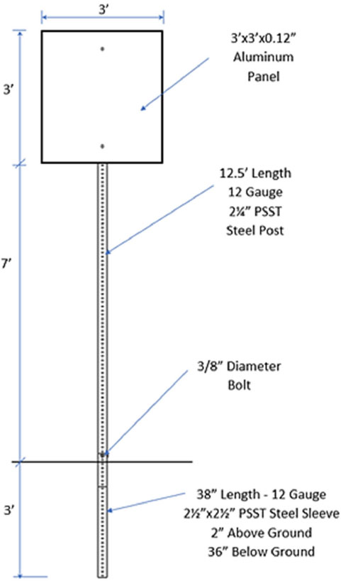
A 12-gauge, 2¼ inch perforated square steel tube (PSST) support manufactured by X2cessories Squared Development & Manufacturing Inc. was installed in standard soil. The overall length of the sign support system was 10.5 feet. The post in this system was anchored to the ground by a 38-inch long, 12-gauge. 2 ½ inch perforated square steel tube sleeve. The sleeve was embedded 36 inches below the ground, and 2 inches above the ground. The sign support was inserted into the ground sleeve 8 inches and was 2 inches below the top of the sign panel. The PSST material was Galvanized steel with ASTM A1011 Grade 50. A 3/8-inch diameter bolt Grade 5, nut, and washer were used to anchor the support to the ground sleeve. A 3-ft (width) x 3-ft (height) x 0.125-inch Aluminum sign was attached to the support using two 3/8-inch diameter hex head bolts Grade 5 with flat washers and nuts. The sign panel was mounted 7-feet, measured from ground level to the base of panel. A side view of the perforated square steel tubing support is shown in Figure 2.
2.2. Material Specifications
This system was selected from typical PSST sign support devices that used standard hardware elements and fabrication methods. The materials and hardware elements delivered met the basic standards in accordance with suppliers or certifications which are on file at the FOIL Office.
2.3. Soil Conditions
The soils at the FOIL have been classified as typical VDOT materials. Soil tests confirmed the compaction and moisture content of the soils were in appropriate ranges consistent with previous testing at the FOIL. These tests, conducted with a nuclear density device, involved repeated measures at multiple positions around the test installation. The FOIL Summary Report documents these results. Pull tests were conducted on the soil the day of the test and found to meet the MASH minimum strength requirement.
3.0. MASH Test Requirements and Acceptance Criteria
Five tests were performed at the FOIL on the PSST Sign Support System. These tests are listed in Table 1 with the vehicles, speeds, angles, offsets, and sign details used in each test. This report summarizes the results of the first test (Test 23012). The set-up and execution of the test followed the prescribed FOIL protocols (including facility ISO requirements) and MASH standards.
Table 1. MASH tests conducted for the Concrete Barrier on an Elevated Curved Ramp
| Test Number | Date | MASH Test | Vehicle | Impact Speed | Impact Angle | Offset | Sign Panel | Outcome |
|---|---|---|---|---|---|---|---|---|
| 23004 | 02/21/23 | 3-61 | Small Sedan | 100 km/hr | 0 | ¼ Driver Side | 1 ft x 1.5 ft x 0.08” | Fail |
| 23006 | 03/08/23 | 3-61 | Small Sedan | 100 km/hr | 0 | ¼ Driver Side | 4 ft x 5 ft x 0.12” | Pass |
| 23008 | 03/22/23 | 3-62 | Pickup Truck | 100 km/hr | 0 | 0 | 4 ft x 5 ft x 0.12” | Fail |
| 23010 | 04/13/23 | 3-62 | Pickup Truck | 100 km/hr | 0 | 0 | 1 ft x 1.5 ft x 0.08” | Pass |
| 23012 | 04/27/23 | 3-61 | Small Sedan | 100 km/hr | 25° | 0 | 3 ft x 3 ft x 0.125” | Fail |
Criteria that must be met under MASH for “Support Structures” fall under three categories: Structural Adequacy, Occupant Risk, and Vehicle Trajectory. Table 2 notes the specific requirements for these criteria, and one or more specific requirements are outlined for each aspect.
Table 2. Test 3-61 evaluation requirements by category.
| Evaluation Category | Requirement |
|---|---|
| Structural Adequacy | B. The test article should readily activate in a predictable manner by breaking away, fracturing, or yielding. |
| Occupant Risk | D. Detached elements, fragments, or other debris from the test article should not penetrate or show potential for penetrating the occupant compartment, or present an undue hazard to other traffic, pedestrians, or personnel in a work zone. Deformation of, or intrusions into, the occupant compartment should not exceed limits set forth in Section 5.3 and Appendix E of MASH (roof ≤4.0 in; windshield = ≤3.0 in; side windows = no shattering by test article structural member; wheel/foot well/toe pan ≤9.0 in; forward of A-pillar ≤12.0 in; front side door area above seat ≤9.0 in; front side door below seat ≤12.0 in; floor pan/transmission tunnel area ≤12.0 in). |
| F. The vehicle should remain upright during and after collision. The maximum roll and pitch angles are not to exceed 75 degrees. | |
H. Occupant impact velocities should satisfy the following:
|
|
I. Occupant ridedown accelerations should satisfy:
|
|
| Vehicle Trajectory | N. Vehicle trajectory behind the test article is acceptable. |
4.0. Test Conditions
4.1. FOIL Test Facility
All testing on this system was performed at the FOIL. The FOIL is a multifaceted impact-testing facility, primarily designed to test the impacts of vehicles with roadside safety hardware, in accordance with the MASH guidelines and standards. The FOIL is an ISO17025-accredited (Cert. # AT-1565) research facility used to support FHWA Safety Research and Development programs and other federal security initiatives.
4.2. Vehicle Tow and Guidance Procedures
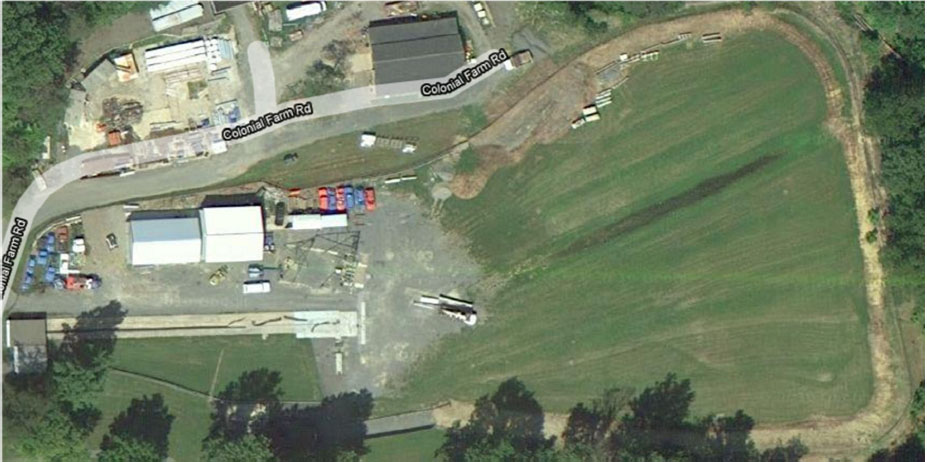
A specially designed FOIL hydraulic-propulsion system pulls the test vehicles into the roadside safety hardware. The vehicles are accelerated on a 220 ft concrete track. The propulsion system is capable of pulling a 17,637 lbs vehicle to over 50 mph. The 2270P test vehicle can be brought to speeds in excess of 70 mph. The test vehicles are released into a 160 x 320 ft runout area. Test articles up to 450 ft in length (typically at 25 degrees relative to the track) can be installed in the runout area at the end of the track. Figure 3 provides an aerial view of the FOIL facility.
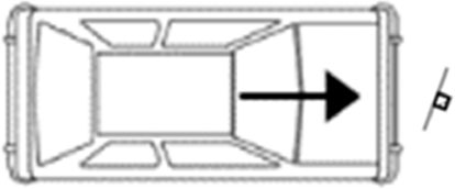
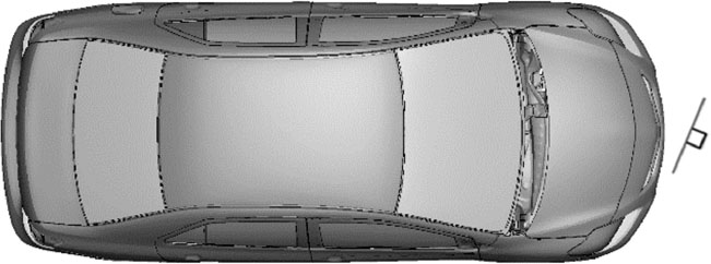
For the sign panel tests, the system was placed perpendicular to the FOIL track to achieve the desired impact point and angle with the system. The system was installed adjacent to the end of the track so the vehicle could be freewheeling and impact at the desired speed and point. Figure 4 depicts the orientations of the sign support system relative to the vehicle.
4.3. Test Vehicle Preparation
MASH Test 3-61 involved a 1100C vehicle weighing 2,420 lbs ± 55 lbs impacting the test article at an impact speed of 62.2 mph ± 2.5 mph and an angle of 0 degrees ± 1.5 degrees. The target impact point for this test was to have the center of sign system aligned with the left (driver side) quarter point of the vehicle. A 2017 Nissan Versa passenger vehicle used in the test. The vehicle weighed 2,577.2 lbs. The vehicle speed was 62.0 mph and the impact angle was 25 degrees. Standard procedures were followed to prepare the vehicle for the test: drain fluids, take accurate measurements of the vehicle, weight, tires, and related features. The vehicle was painted blue to maximize the viewability of the impact outcomes in the high-speed videos.
4.4. Data Acquisition Systems
4.4.1. Vehicle Instrumentation and Data Processing
Accelerometers, rate transducers, and speed measuring devices captured the vehicle and barrier responses during impact. Two tri-axial accelerometers mounted at the vehicle center of gravity measured the x-, y-, and z-accelerations of the vehicle. This data was used to compute the occupant ride-down acceleration and occupant-impact velocities. Additionally, two tri-axial rate transducers measured the vehicle roll, pitch, and yaw rates. Contact switches installed on the vehicle and test article synchronized “time zero” of the impact for the sensor data and high-speed video imagery.
4.4.2. Photographic Instrumentation and Data Processing
Seven high-speed cameras were used for full-scale crash tests. One camera was placed over the impact region to capture an overhead view. Six additional cameras were placed at different locations surrounding the impact region to capture left, right, front, rear, and isometric views of the crash event. Additionally, a real time camera was used to capture the rear view of the crash. The test data from the sensors and cameras was downloaded immediately after the test to document the crash event and the behavior of the system.
4.5. Test Setup Conditions
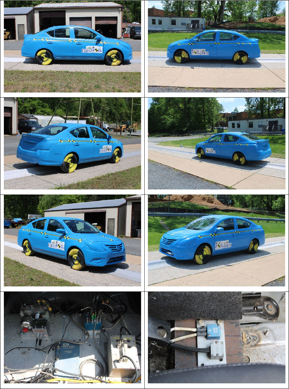
4.5.1. Test Vehicle
Figure 5 shows photos from the 2017 Nissan Versa passenger vehicle used for the crash test. Test inertial weight of the vehicle was 2,413.0 lbs and its gross static weight was 2,569.5 lbs. The height of the vehicle bumper lower edge was 16.1 in, and the upper edge was 21.3 in. The height to the vehicle’s center of gravity sensor was 15.5 in. The test used the cable reverse tow and guidance system to direct the vehicle into the installation that then released the vehicle in a freewheeling and unrestrained mode just prior to impact.
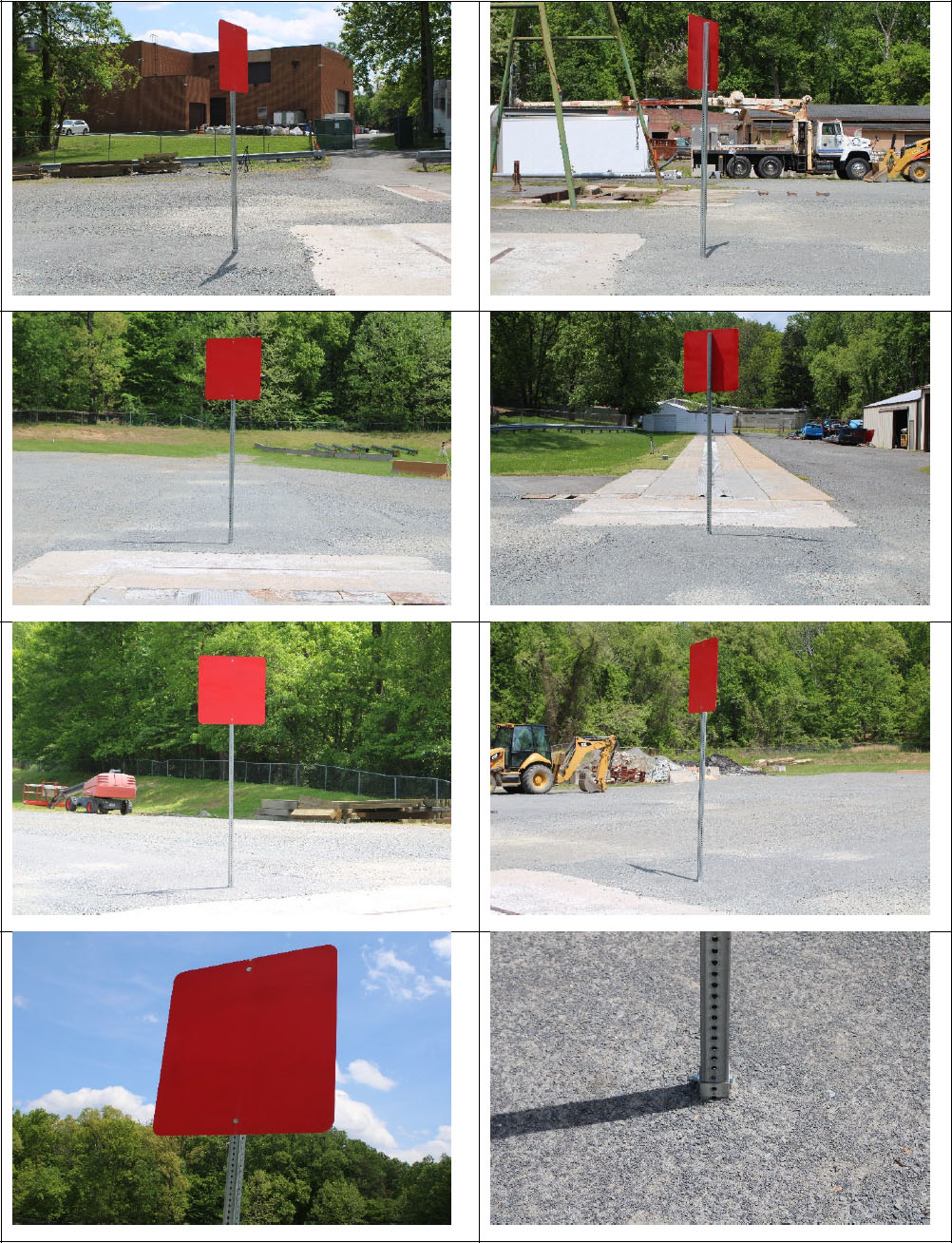
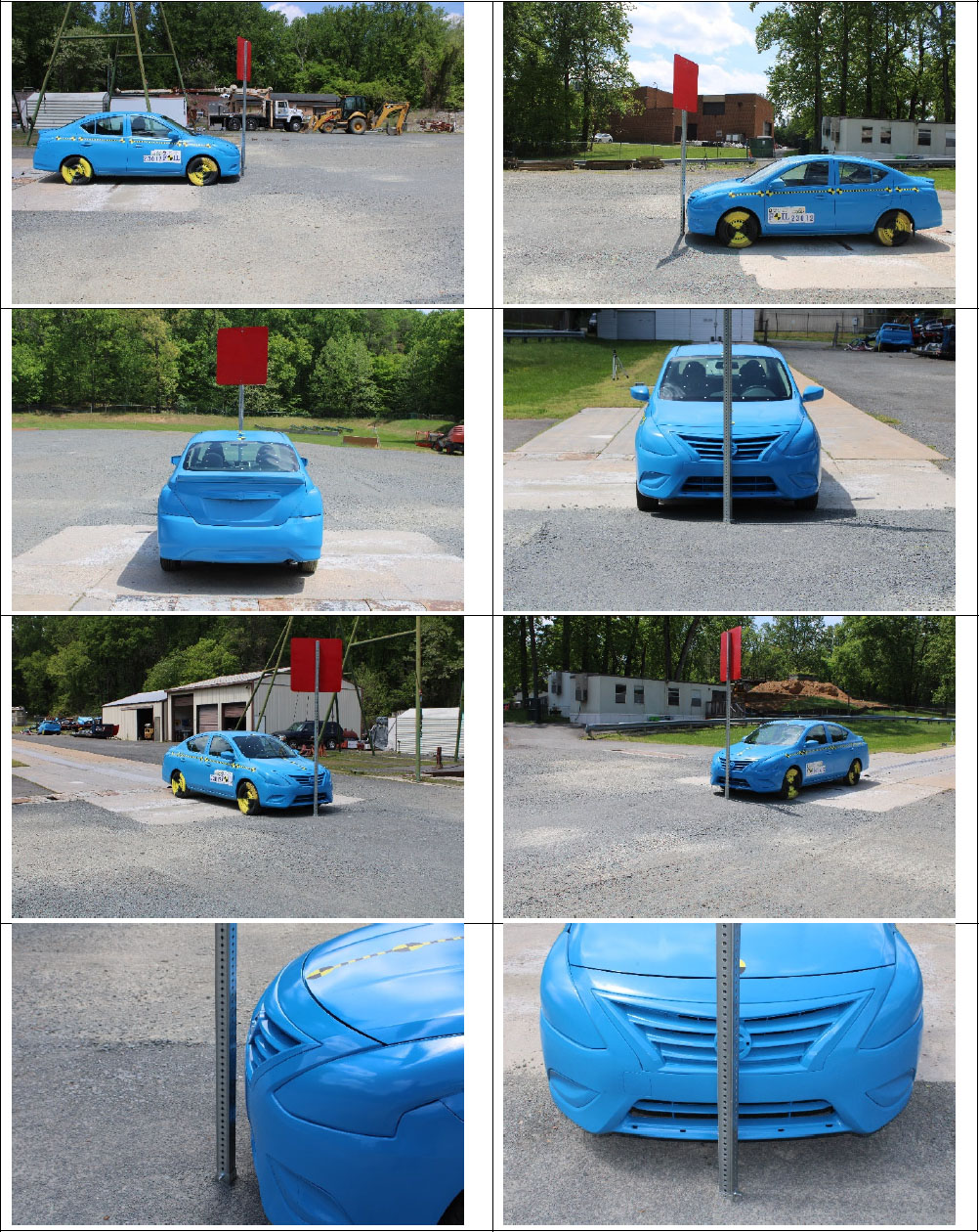
4.5.2. Test Article
Figure 6 shows several views of the installed sign support system prior to the test. Figure 7 shows eight views of the test vehicle in proximity to the test article used to document the static interface of vehicle and the system elements. Pictures documenting construction of the test article are available, along with any related compaction, material strengths, or other features of the test article that may become relevant.
5.0. Crash Test Documentation
5.1. Test Designation and Impact Conditions
For test 23012, the sign support was impacted with a 2017 Nissan Versa vehicle traveling at 62.0 mph and an impact angle of 25 degrees and no offset, as planned. Figure 8 shows the planned test setup.
5.2. Crash Test 23012 Outcome (for MASH Test 3-61)
5.2.1. General Conditions at Time of Test
The test was performed on April 27, 2023, at 10:00 p.m. Weather conditions at the time of testing were:
- Sunny.
- Wind speed and direction: 6 mph from the Northeast.
Conditions were considered to have negligible effects on the outcome of the test.
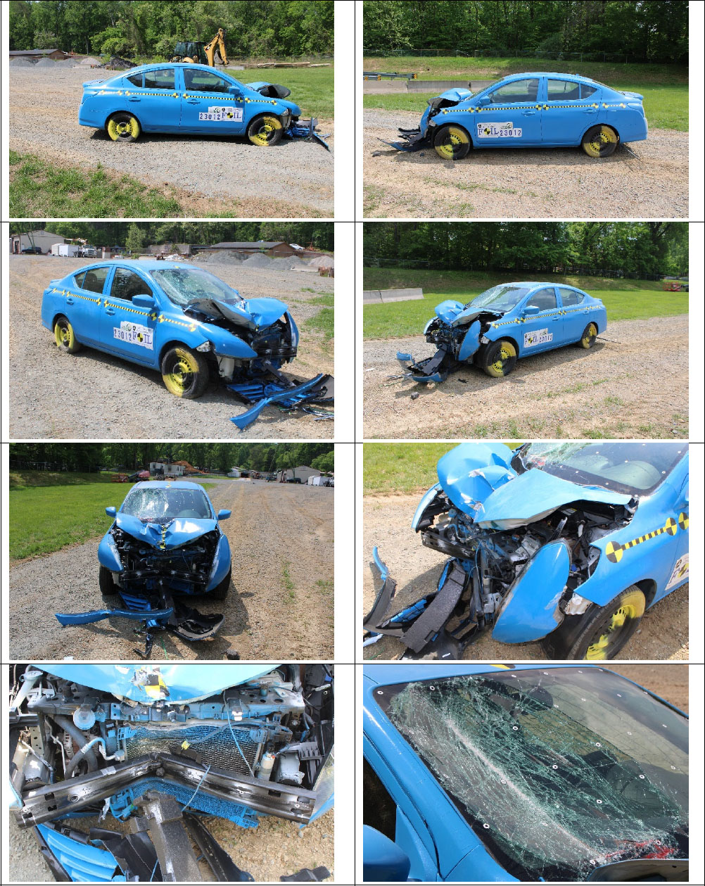
5.3. Test Article and Vehicle Damage
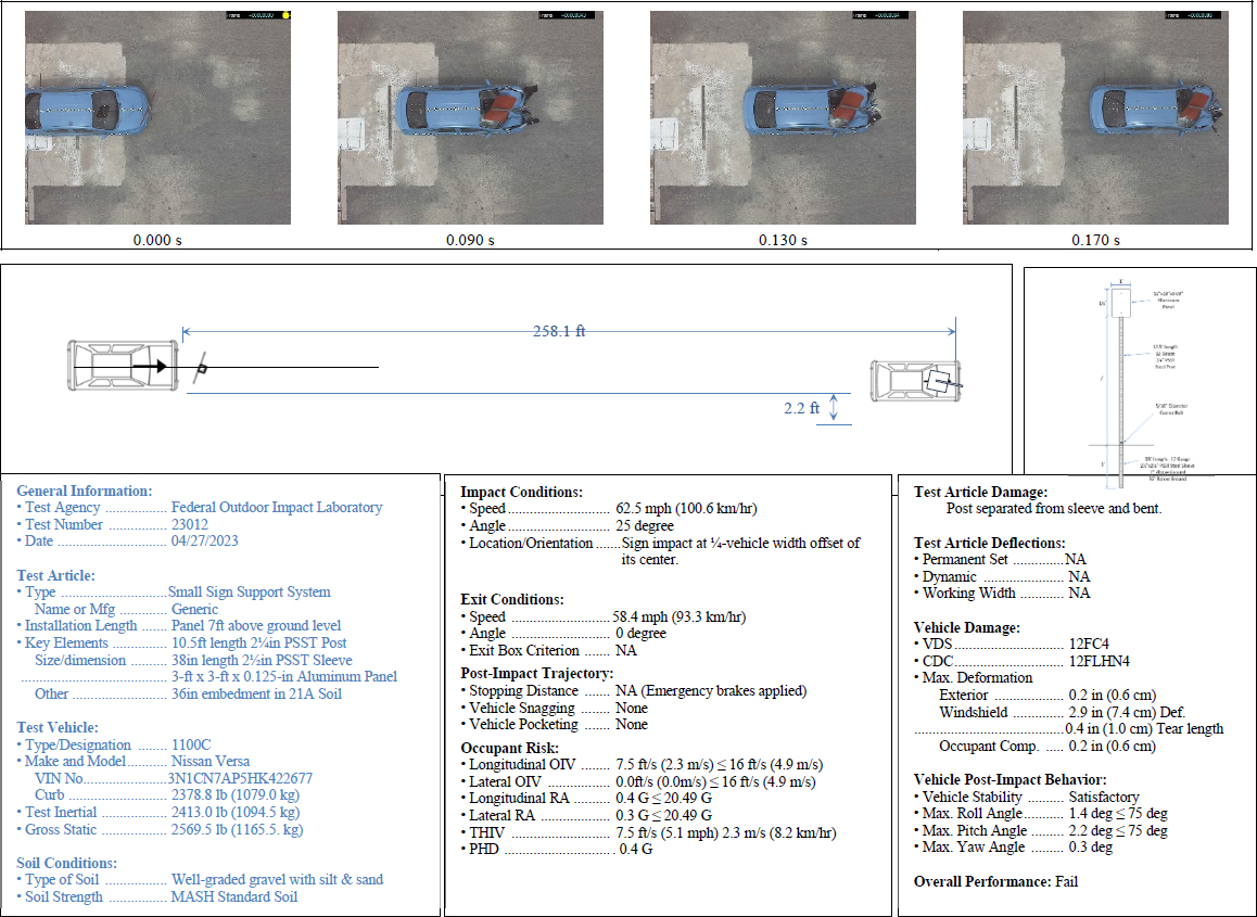
The vehicle contacted the system as shown in Figure 9 and came to rest (after the brakes were applied) 258.1 ft downstream.
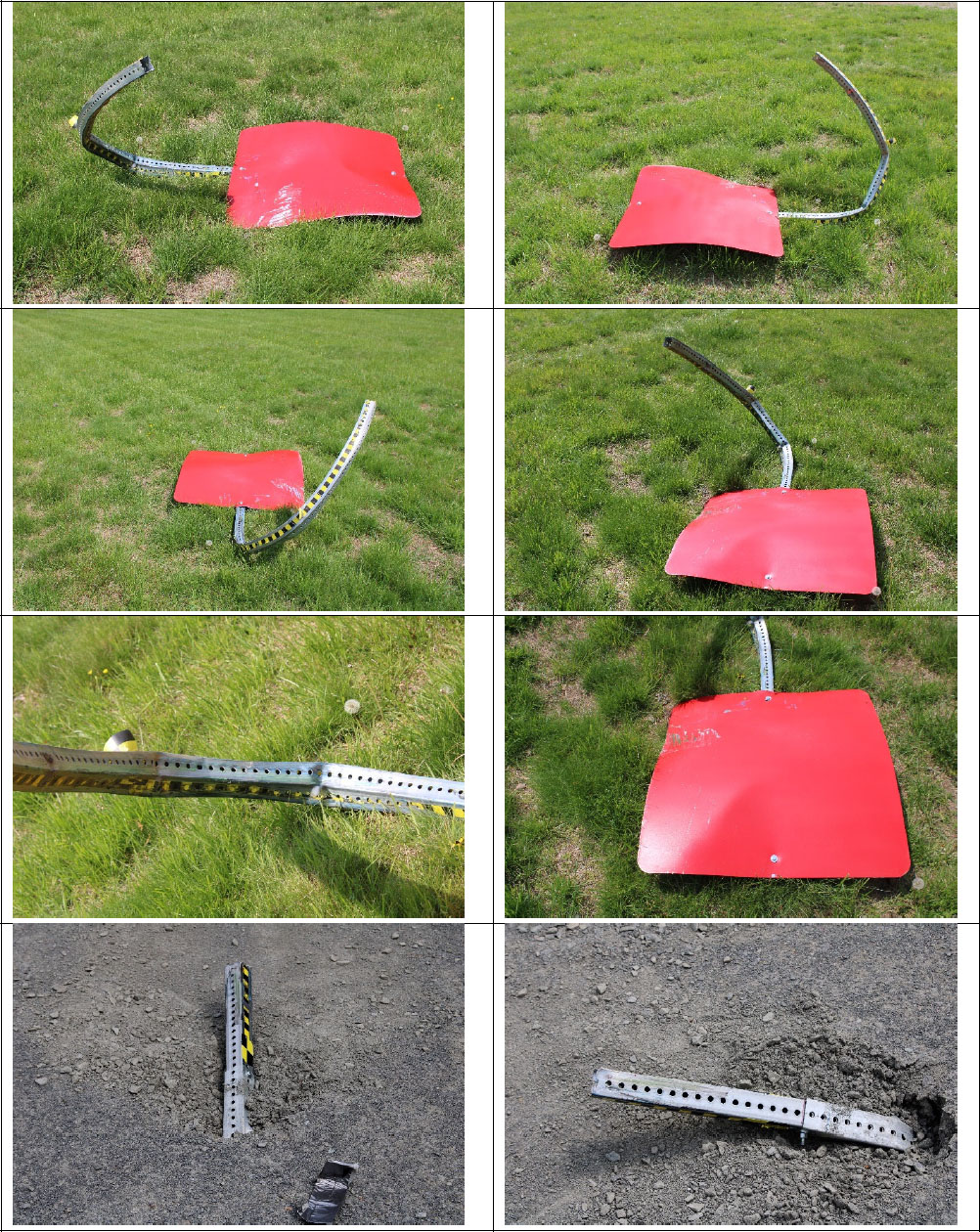
Figure 9 shows various views of the damage to the test vehicle. The figure shows significant damage to the front of the vehicle. The impact damaged the front bumper, the fascia, radiator, and the hood. There was extensive damage to the windshield, and it resulted in a tear of the polymer layer. Figure 10 shows various views of the sign support system.
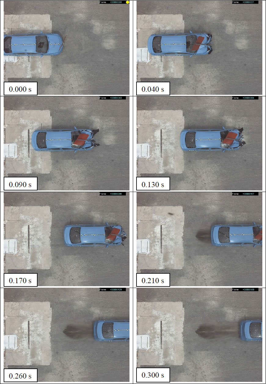
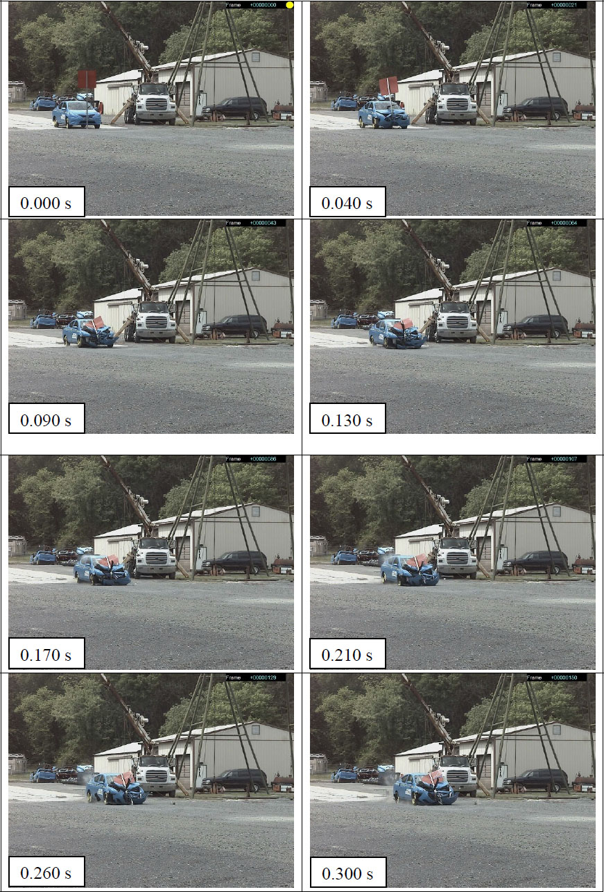
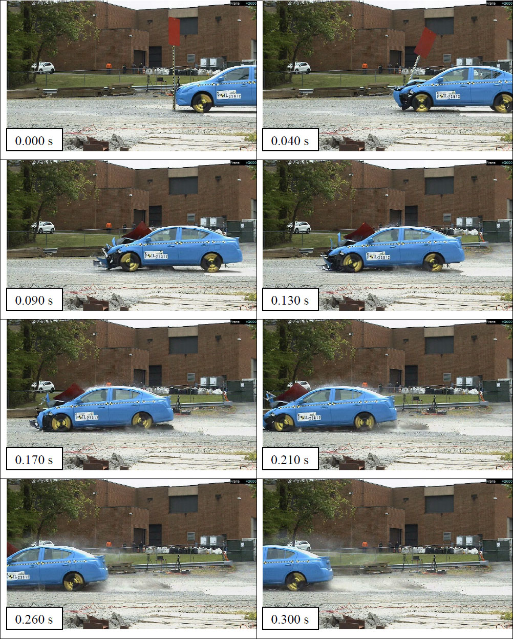
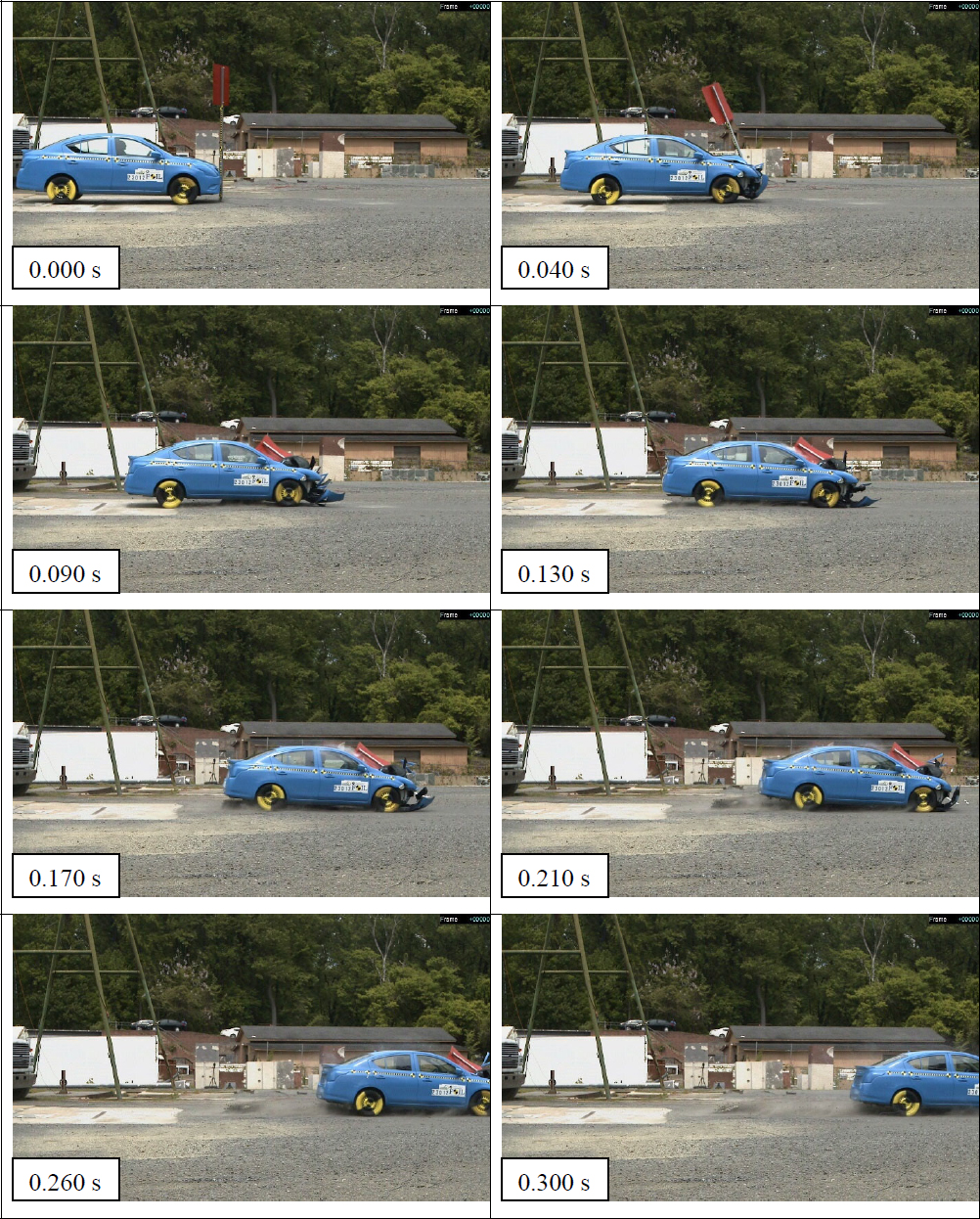
Figures 11 to 14 show various views of the crash sequence from overhead, rear, left side, and the right side of the system. Table 3 lists some of the events occurring over the duration of the crash. The left side view in Figure 13 provides the best perspective on the functioning of the system.
Table 3. Events during Test 3-61 (Test No. 23012).
| TIME (s) | EVENT |
|---|---|
| 0.000 | Vehicle touches the sign support post after release from the pull-system. |
| 0.040 | The PSST starts deforming around the vehicle front bumper and hood. The sign panel starts being pulled-down with the post. The PSST pulled-out of the sleeve. |
| 0.090 | The PSST continues to bend and the sign drops lower to touch the windshield. The PSST bends more while the post wrapped around the front of the vehicle (hood and bumper). |
| 0.130 | The sign panel deflects the windshield and causes a tear into the polymer layer. The post starts wrapping around the vehicle front. |
| 0.170 | The sign panel stays in contact with the windshield and causes tear to the polymer layer. The post is still wrapped to the vehicle front. |
| 0.210 | The sign panel and the PSST post continues to move forward together. |
| 0.260 | The sign panel and the PSST post continues to move forward together. |
| 0.300 | The sign panel and the PSST post continues to move forward together. |
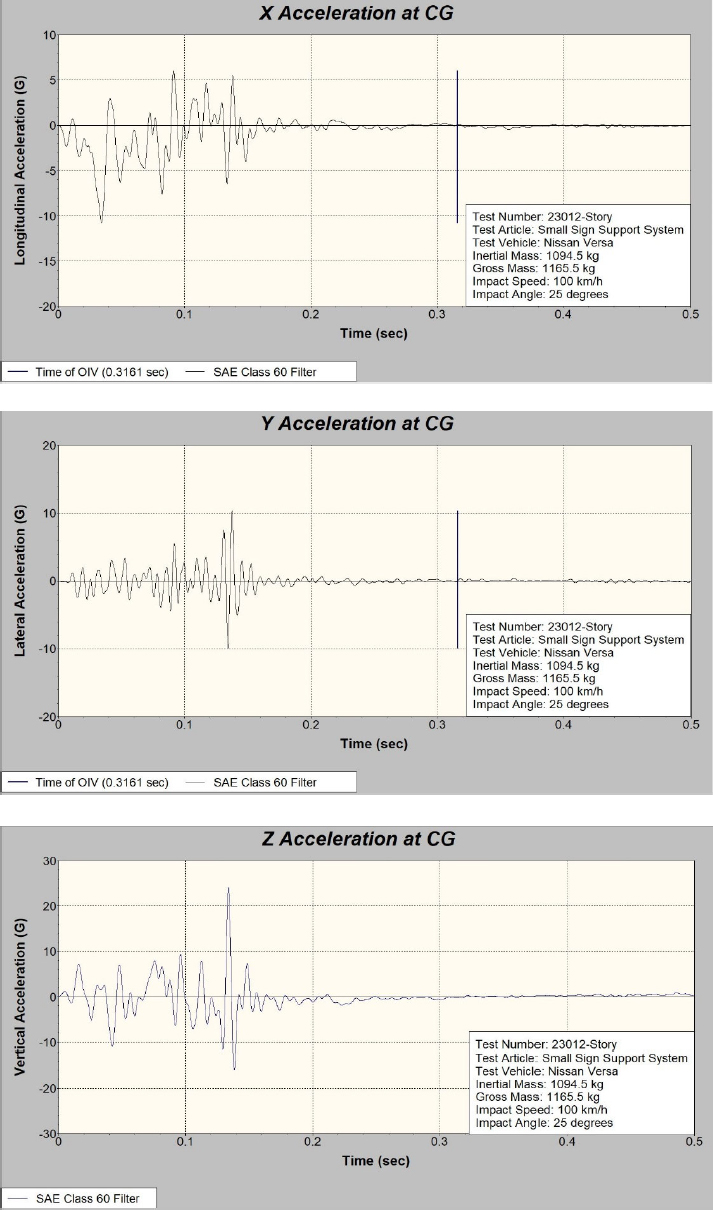
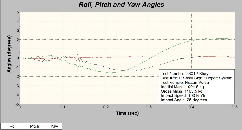
Figure 15 shows the filtered accelerations/decelerations during the crash event. Images show typical patterns of oscillation for the x-, y-, and z-axis measurements. Figure 16 shows plot of the vehicle roll, pitch, and yaw extracted from the data measured using the rate transducers.
5.4. MASH Evaluation
Table 4 provides the critical occupant risk data for Test 3-61 (Test No. 23012). These metrics were derived from the accelerometer located at the vehicle center of gravity. Table 5 cites the specific MASH requirements for the Test 3-61 in the first column. The Results column indicates the specific conclusions drawn from the test outcome. The last column notes whether results meet the requirements. In all cases, a PASS was considered appropriate.
Table 4. Occupant risk factors – Test 3-61 (Test No. 23012).
| Occupant Risk Factor | Value | Time | |
|---|---|---|---|
| Occupant Impact Velocity (OIV) ft/s | Longitudinal | 7.5 | 0.3161 sec |
| Lateral | 0.0 | 0.3161 sec | |
| Occupant Ridedown Acceleration G | Longitudinal | -0.4 | 0.3547 - 0.3647 sec |
| Lateral | 0.3 | 0.3168 - 0.3268 sec | |
| Theoretical Head Impact Velocity (THIV) ft/s | 7.5 | 0.3161 sec | |
| Post Head Deceleration (PHD) G | 0.4 | 0.3547 - 0.3647 sec | |
| Acceleration Severity Index (ASI) | 0.3 | 0.0399 - 0.0899 sec | |
| Maximum 50-m/s Moving Average | Longitudinal | -3.7 | 0.0211 - 0.0711 sec |
| Lateral | 0.9 | 0.0828 - 0.1328 sec | |
| Vertical | 2.0 | 0.0469 - 0.0969 sec | |
| Maximum Roll, Pitch, and Yaw Angles, deg. | Roll | -1.4 | 0.2592 sec |
| Pitch | 2.2 | 0.4449 sec | |
| Yaw | 0.3 | 0.4026 sec | |
Table 5. Review of MASH results for Test 3-61, Test No. 23012.
| MASH Requirement | Results | Status |
| B. The test article should readily activate in a predictable manner by breaking away, fracturing, or yielding. | Posts separated from sleeve upon impact. | Pass |
| D. Detached elements, fragments, or other debris from the test article should not penetrate or show potential for penetrating the occupant compartment, or present an undue hazard to other traffic, pedestrians, or personnel in a work zone. | The sign blank impact windshield but deformation was less than 3 in but there was 0.4 in tear of the windshield plastic liner. No other elements of the test article penetrated or show potential for penetrating the occupant compartment, or present an undue hazard to other traffic, pedestrians, or personnel in a work zone. | Fail |
| Deformation of, or intrusions into, the occupant compartment should not exceed limits set forth in Section 5.3 and Appendix E of MASH (roof ≤4.0 in; windshield = ≤3.0 in; side windows = no shattering by test article structural member; wheel/foot well/toe pan ≤9.0 in; forward of A-pillar ≤12.0 in; front side door area above seat ≤9.0 in; front side door below seat ≤12.0 in; floor pan/transmission tunnel area ≤12.0 in). | All occupant compartment intrusions were less than the MASH critical values. Roof: <0.1 in ≤ 4.0 in Windshield: 2.9 in ≤ 3.0 in (0.4 in Tear) Side windows: No shattering wheel/foot well/toe pan: <0.1 in ≤ 9.0 in Side front panel forward of A-pillar: 0.2 in ≤ 12.0 in Front side door area above seat: 0.2 in ≤ 9.0 in Front side door below seat: 0.2 in ≤ 12.0 in Floor pan/transmission tunnel area: 0.2 in ≤ 12.0 in. |
Fail |
| F. Vehicle should remain upright during and after collision. The maximum roll and pitch angles are not to exceed 75 degrees. | The vehicle remained upright during and after the collision event. Maximum Roll: 1.4 deg ≤ 75 deg Maximum Pitch: 2.2 deg ≤ 75 deg. |
Pass |
|
H. Longitudinal Occupant Impact Velocities should satisfy the following:
Preferred: 10 ft/s (3.0 m/s) Maximum: 16 ft/s (4.9 m/s) |
Longitudinal occupant impact velocity was 7.5 ft/s ≤ 16 ft/s | Pass |
|
I. Longitudinal and Lateral Occupant Ridedown Accelerations should satisfy the following:
Preferred Maximum 15.0 G to 20.49 G |
Maximum longitudinal occupant ridedown acceleration was 0.4 G ≤ 20.49 G, and maximum lateral occupant ridedown acceleration was 0.3 G ≤ 20.49 G. | Pass |
| N. Vehicle trajectory behind the test article is acceptable. | Pass |
6.0. Conclusions and Recommendations
Test 23012 was deemed not to meet MASH requirement. It showed that the sign system hit the windshield and caused a tear. The crucial occupant-risk values were in acceptable ranges, indicating that occupants would be likely to survive the crash. Figure 17 includes a summary of test results.
7.0. References
21. FHWA FOIL. Crash Test 23012 Summary Report. Prepared by CCSA, George Mason University, Fairfax, VA, 2022.
22. American Association of State Highway and Transportation Officials, Manual for Assessment of Safety Hardware (MASH), Washington, D.C., 2016.
23. American Association of State Highway and Transportation Officials, Roadside Design Guide, Washington, D.C., 2011.
24. FHWA FOIL. Crash Test 19014-C Summary Report. Prepared by CCSA, George Mason University, Fairfax, VA, 2019.
25. Bullard, L., Bligh, R., Menges, W., Haug, R., NCHRP Document 157: Volume I: Evaluation of Existing Roadside Safety Hardware Using Updated Criteria – Technical Report, NCHRP Project 22-14(03), College Station, Tx, March 2010.